


Digital Inputs
The drive provides 8 digital inputs on X21. Dual axis drives and drives with built-in option IO or DX offer additional 4 inputs on X22 and 2 programmable Input/Outputs on X22. If X23 is built-in and not used for feedback or EEO function, then it offers 4 additional programmable Input/Outputs.
All inputs can be used to initiate pre-programmed actions. A list of actions is included in WorkBench. If an input is programmed, it must be saved to the drive.
The drive provides 4 safe digital inputs on X21 and X22. These inputs can be used as safe inputs, based on the installed functional option (see "Technical Data")(see "Safe Digital Inputs").
|
|
Maximum distance for unshielded I/O lines is 3 m inside the cabinet. If the I/O cable leaves the cabinet, it must be EMC shielded. |
|
|
Depending on the selected function, the inputs are high or low active. Digital input filter can be set in WorkBench to change sensitivity of the inputs. |


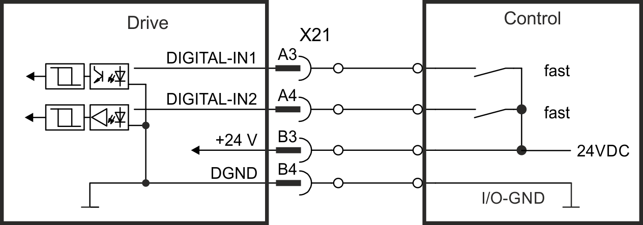
Digital-In 1 and 2
These inputs (IEC 61131-2 Type 1) are particularly fast and are therefore suitable for position latch functions. They can also be used as 24 V inputs for electronic gearing (see "Gearing").
Technical characteristics
- Floating, reference common line is DGND
- High: 15 to 30 V/2 to 15 mA , Low: -5 to +5 V/<15 mA
- Update rate: firmware reads hardware input state every 250 µs
- High accuracy latch: motor feedback position or interpolated time is latched or captured within 2 µs of input signal transition (with digital input filter set to 40 ns)
- The AKD2G capture engine is polled every 62.5 µs (16 kHz) by the firmware
Wiring example
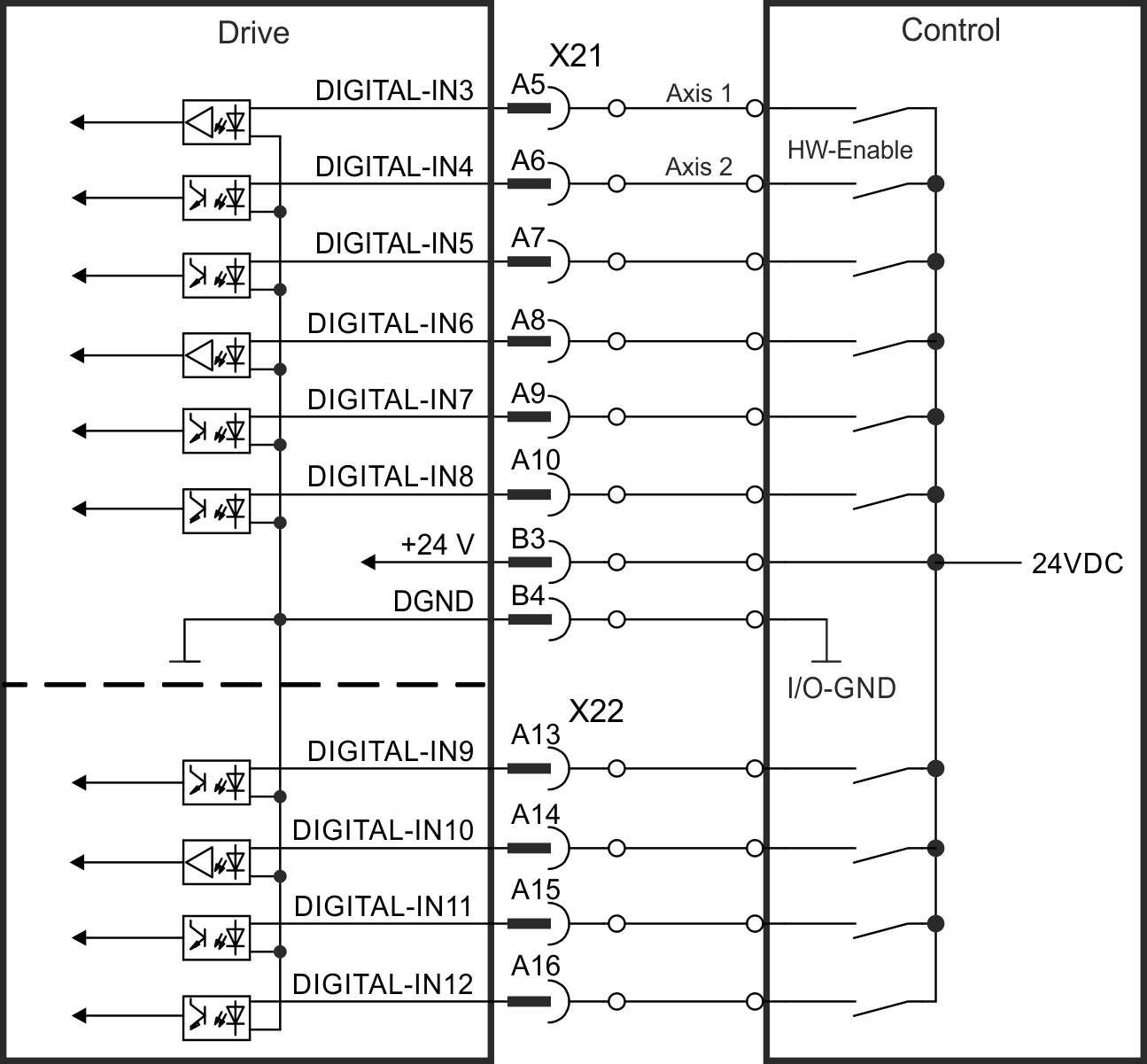
Digital-In 3 to 12
These inputs (IEC 61131-2 Type 1) are programmable with WorkBench.
Manufacturer setting:
- Digital-In 3: HW-Enable Axis 1
- Digital-In 4: HW-Enable Axis 2
- Digital-In 5 ...12: off
Choose the function you require in WorkBench and refer to the software for more information.
Technical characteristics
- Floating, reference common line is DGND
- High: 15 to 30 V/2 to 15 mA , Low: -5 to +5 V/<15 mA
- Update rate: firmware reads hardware input state every 250 µs
Wiring example
Digital-In/Out 1 and 2
Pins X22/A20-A21 (Digital-In/Out 1) and X22/B20-B21 (Digital-In/Out 2) can be defined as either inputs or outputs. For programming refer to WorkBench.
|
|
NOT compatible with 24V signal level! Will be damaged if connected to +24V! |
Technical characteristics when configured for input:
- RS485 common is AGND; not optically isolated
- No wire break detection
- Termination Selection: Unterminated or DC Terminated
- Differential or Single-ended
- For single-ended:- Negative terminal is open circuit; Positive input high signal = 3 - 5 V.
- Force input high with 5 V driver applied to DIO1/2+; pull input low by sinking DIO1/2+ to AGND.
Open circuit (floating) input will typically be high.
- Update rate: firmware reads hardware input state every 250 µs
- When used for capture, timing resolution is <1 µs
Wiring example

Digital-In/Out 3 to 6
X23 can be used for digital I/O. The channels can be defined as inputs or outputs. For programming refer to WorkBench.
|
|
NOT compatible with 24 V signal level! Will be damaged if connected to +24 V! |
Technical characteristics when configured for input:
- RS485 reference common line is 0 V
- No wire break detection
- DIO 3/4 Termination Selection: Unterminated (AC Termination) or DC Terminated
- DIO 5 Termination Selection: Unterminated (AC Termination) or DC Terminated on newer models*
- DIO 6 Termination Selection: Unterminated (AC Termination) Only
- Differential only
- Update rate: firmware reads hardware input state every 250 µs
- When used for capture, timing resolution is <1 µs
Wiring example